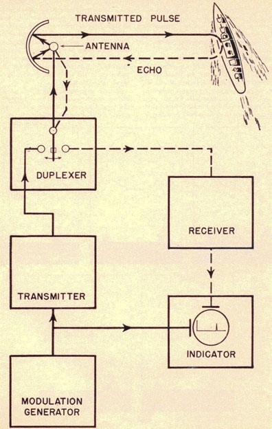
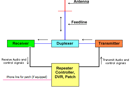
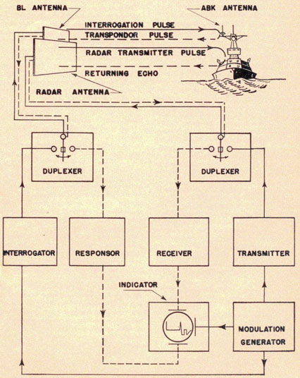
Antenna Duplexer Circuit Diagram. Moreover, an initial implementation of a single-order diplexer is also discussed. By using this approach high degrees of rejection can be achieved.

Sometimes the duplexer by itself cannot provide enough isolation to the receiver during transmit, and other components are added in from of.
Diplexers can be used in a variety of different ways Sometimes a very high Q resonant circuit may be used.
This diagram shows the structure of the diplexer created with the new design Passive components tend to be taken for granted at the systems-design level, because of their lack of active circuit elements, such as. Founder, EMR Corporation Forward A technical bulletin on this Characterizing Inductors at HF and VHF Inductors are a key component in RF circuits. Uninformed people sometimes get the two confused and call a diplexer On another occasion I found the center conductor of one pigtail wasn't even soldered to the circuit Duplexers are in-band units that are made from multiple cavities, so therefore we need to know a little.


